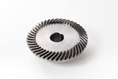
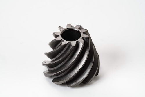
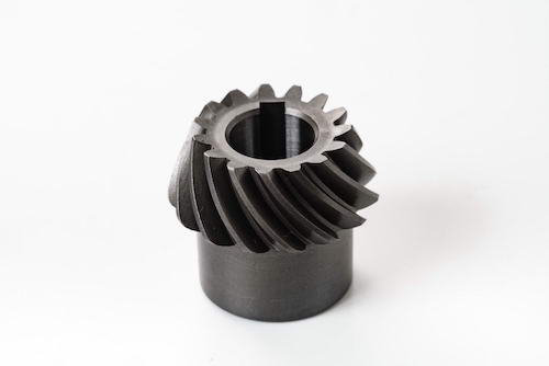
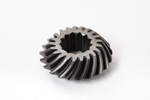
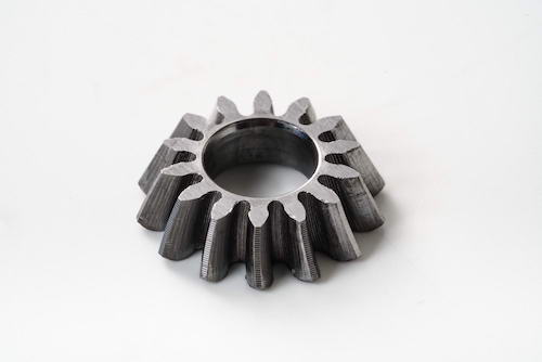
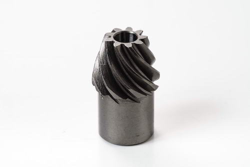
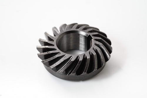
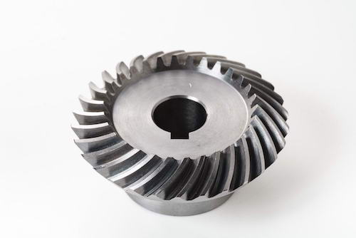
Custom Spiral Bevel & Miter Gears
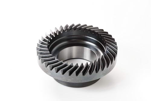
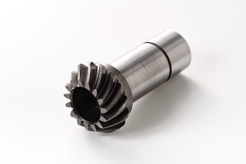
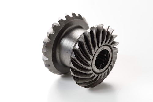
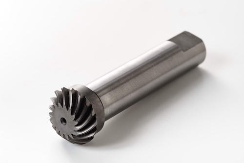
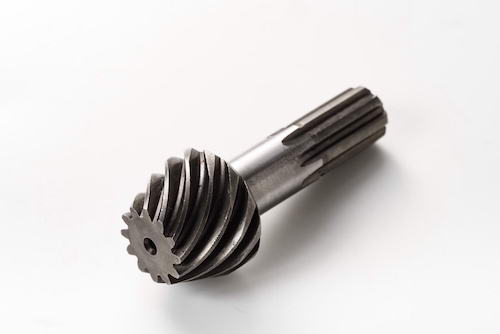
Bevel gears are conical gears designed to transmit motion between intersecting axes. While they typically transfer rotation between two shafts arranged at right angles, they can be engineered for almost any shaft angle.
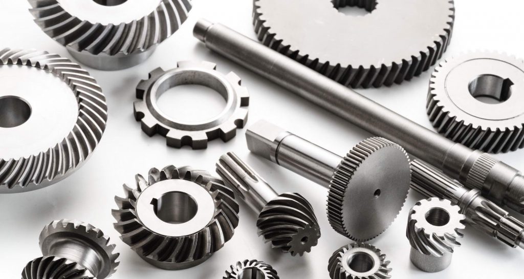
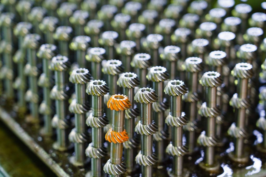
Narutaki Industries specializes in manufacturing small gears—particularly spiral bevel gears. We produce spiral bevel gears in diameters ranging from 6 mm to 120 mm and can work with a variety of materials to meet our customers’ needs. Drawing on our expertise, we partner with clients across many sectors and satisfy even the most demanding application requirements.
Bevel gears are widely used not only in automotive, heavy machinery, industrial, aerospace, and marine fields, but also in simple hand tools such as drills and planers. With more than 30 years of gear-manufacturing experience, we pour our know-how into every gear we make. Our products are highly regarded for their stability, precision, and reliability.
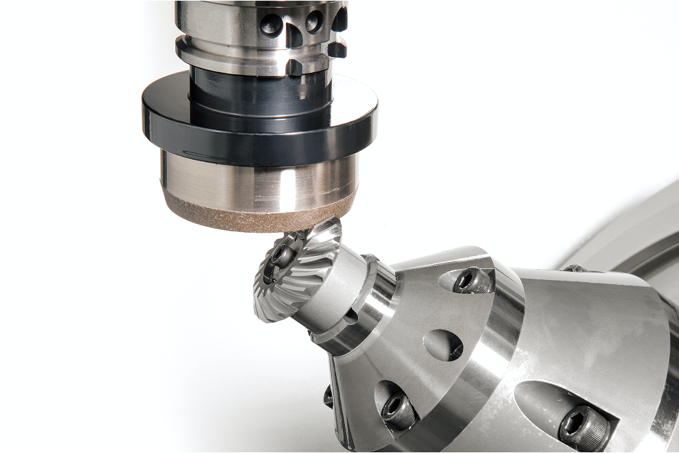
We are experts at cutting spiral bevel gears on five-axis multitasking machines, ensuring high-precision machining. We also supply machined products such as flat (spur) gears and helical gears. Whatever the size of your order—standard or custom—Narutaki Industries is ready to support your next gear project.
Available Specifications
| Item | Specifications | |
|---|---|---|
| Number of Modules | 0.3 - 4 | |
| Diametral Pitch | 6.5 - 80 | |
| Outer Diameter | Φ6 - φ100 | |
| Spiral Angle | 0 - 40°(actual) | |
| Gear ratio | 1:1 - 1:10 | |
| Shaft angle | 35 - 135° | |
| Hardening method | high-frequency induction hardening nitriding treatment carburizing hardening |
|
| Machining Material | Carbon Steel | S45C(AISI 1045) |
| Alloy Steel | SCM415(AISI 4115), SCM420(AISI 4118), SCM435(AISI 4135), SCM440(AISI 4140), SNCM420(AISI 4320) | |
| Stainless Steel | SUS304(AISI 304) | |
| Plastic | POM (Polyoxymethylene), Nylon, Other Engineering Plastics | |
| Machining Equipment | 5-axis multi-tasking machine DMG Mori, NTX1000 | |
| Spiral Bevel Gear SBG-10×11 | ||
| CNC Cylindrical Grinder, E300G | ||
| NC grinding machine for spiral bevel gears (module: MAX.4, DP: MIN.6.5) | ||
Custom-made Product Examples
Alloy Steel
Module: 1.0
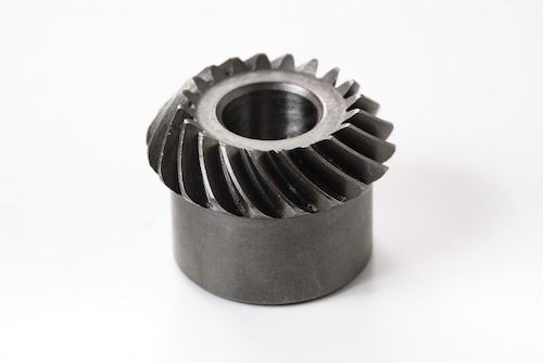
- Material: SNCM420
- Module: 1.0
- Number of teeth: 20
- Helix angle: 35°
Module: 1.25
Module: 1.3
Module: 1.5
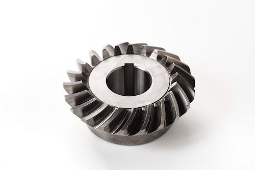
- Material: SCM415(AISI 4115)
- Module: 1.5
- DP: 16.9
- Number of teeth: 21
- Helix angle: 35°
Module: 2.0
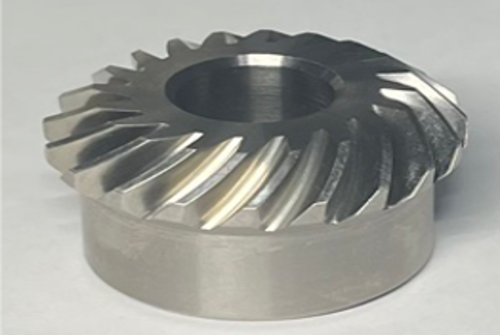
- Material: Titanium(Ti-6AL-4V)
- Module: 2.0
- Number of teeth: 20
- Helix angle: 35°
DP: 18
Aluminum
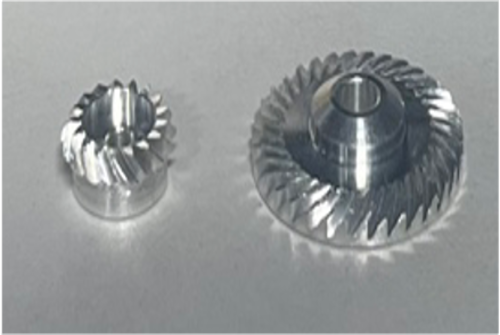
- Material: A5052
- Module: 0.4
- Teeth ratio: 17:34
- Helix angle: 35°
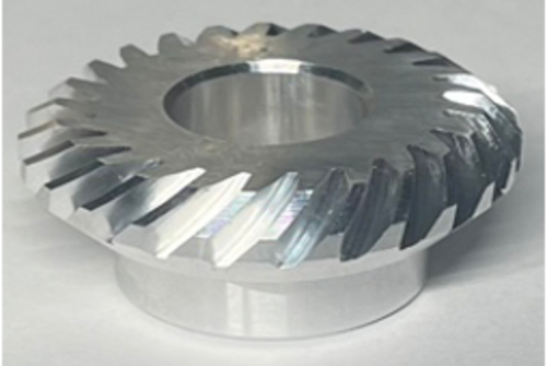
- Material: A7075
- Module: 1.5
- Number of teeth: 25
- Helix angle: 35°
Plastic
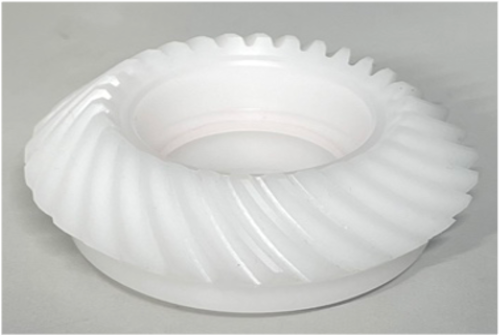
- Material: POM
- Module: 2.0
- Number of teeth: 30
- Helix angle: 35°
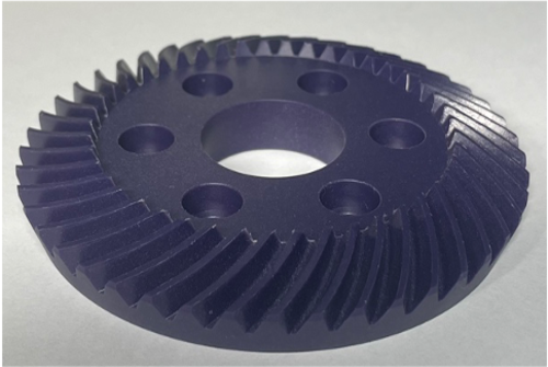
- Material: MC703HL
- Module: 2.0
- Number of teeth: 45
- Helix angle: 35°
Basics of Spiral Bevel Gears
What is Spiral Bevel Gears?
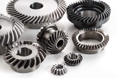
Spiral bevel gears feature a curved tooth pattern on a pitch cone along with a torsion angle. They offer smoother motion transmission compared to straight bevel gears or Zerol bevel gears (as explained below), resulting in significant noise and vibration reduction at high speeds (10 m/s or more).
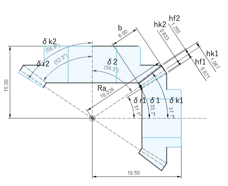
What makes Spiral Bevel Gears Unique?
In the case of spur gears, for instance, when cutting gears with a module of 1, you can utilize a hob (cutting tool) with a module of 1, regardless of the tooth ratio. However, when it comes to spiral bevel gears, the theoretical cutter diameter is determined by considering various factors, including the tooth ratio, tooth width, torsion angle, and gear module. The theoretical cutter diameter can vary significantly based on these specifications mentioned earlier.
In essence, even if you have numerous cutters, they may not suffice because the same module can yield different theoretical cutter diameters depending on the tooth ratio. This implies that a standardized approach is needed.
Currently, when cutting small modules like ours (2.5 modules or smaller), cutter diameters are standardized to some extent, such as 0.5 inch, 1.1 inch, 1.5 inch, 2 inch, and 3.5 inches. A standard cutter is selected to approximate the theoretical cutter diameter calculated based on the various specifications. For example, if the theoretical cutter diameter is 1.2 inches, you can choose either a 1.1 inch or 1.5 inch standard cutter.
Considering that standard cutters are further adjusted based on factors such as cutter No. (blade tilt angle) and point width (cutting edge width) in accordance with gear specifications, it becomes evident that a substantial quantity of cutters is still required.
Therefore, despite the theoretical complexity of spiral bevel gears, they represent an appealing choice for manufacturers due to their high degree of adaptability.
Uses of Spiral Bevel Gears

1. Automotive Industry
In the realm of automobiles, spiral bevel gears are pivotal in the differential system, ensuring drive wheels can rotate at different speeds during turns. Their smooth meshing attributes make them ideal for quieter operations. Additionally, they're incorporated in specific transmission setups and are fundamental in 4WD vehicles, facilitating balanced power distribution to both front and rear axles.
2. Industrial Equipment
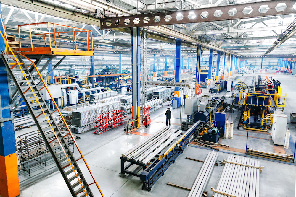
Industrial machinery, especially those requiring power to be transferred at right angles, heavily relies on spiral bevel gears. They're a common sight in power tools like drills, where direction change is essential, and in conveyor systems, ensuring materials move smoothly across different levels.

3. Marine Industry
Marine vessels utilize spiral bevel gears in their propulsion mechanisms, transferring power efficiently from engines to propellers. Their precision also finds use in advanced navigation systems, allowing for accurate steering and movement in the vast marine environment.
Manufacturing Process
STEP 1: Material Preparation

The appropriate material is selected based on desired gear properties, ensuring optimal strength and durability.
STEP 2: Cutting
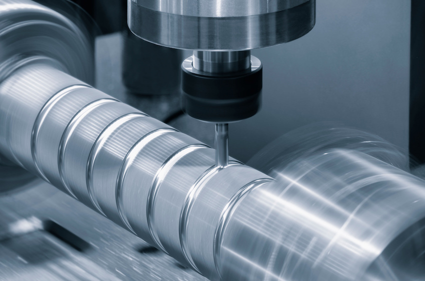
The chosen material is cut into manageable sizes, preparing it for subsequent processing.
STEP 3: Heat Treatment
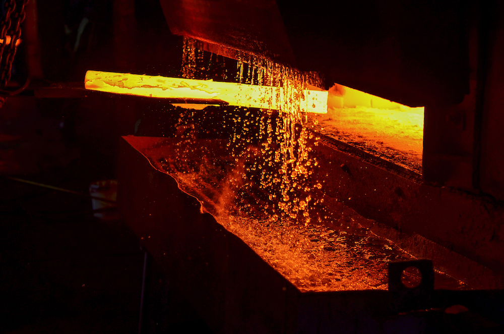
The cut pieces undergo heat treatment to enhance their mechanical properties, such as hardness and toughness.
STEP 4: Lathe Machining
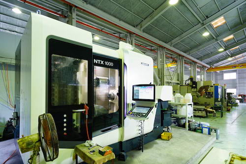
The heat-treated pieces are shaped on a lathe, ensuring symmetry and preparing them for detailed machining.
STEP 5: Gear Cutting
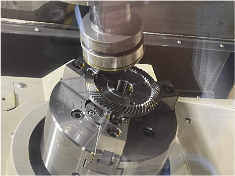
The teeth of the gear are formed using specialized gear cutting machines, creating the unique helical shape.
STEP 6: Broaching
Internal features, like keyways or splines, are created using a broaching process, which removes material with a toothed tool.
STEP 7: Carburizing with high frequency
The gear undergoes a carburizing process, enriched with carbon, and is then treated with high-frequency heat to harden its surface.
STEP 8: Shaft Grinding
The gear's shaft is finely ground to achieve precise dimensions, ensuring a perfect fit in its assembly.
STEP 9: Gear grinding

The gear teeth are finely ground using specialized equipment, ensuring smooth engagement and precise tooth profiles, enhancing the gear's operational performance.
STEP 10: Inspection
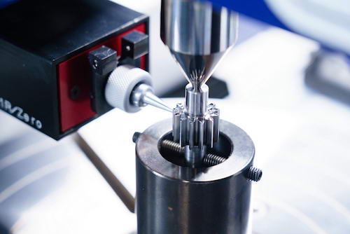
The final gear is rigorously inspected for quality and compliance with design specifications. Advanced tools and machines are used to measure dimensions, alignments, and other critical parameters to guarantee optimal performance in real-world applications.
FAQs about Spiral Bevel Gears
Q.1: What is the difference between Spiral/Straight Bevel Gears?
A.1: spiral bevel gears have curved teeth that are helical in shape, allowing for smoother and quieter operation due to gradual tooth engagement. This design also distributes the load over several teeth, providing better strength and durability. In contrast, straight bevel gears have straight teeth that engage all at once, leading to sudden load application and potentially noisier operation.
Q.2: What is the "Efficiency" of Spiral Bevel Gears?
A.2: The efficiency of spiral bevel gears typically ranges from 94% to 98%, depending on the design, lubrication, and load conditions. Their helical tooth design ensures smooth tooth engagement, reducing friction and energy losses, which contributes to their high efficiency.
Q.3: Are Spiral Bevel Gears bidirectional?
A.3: Yes, spiral bevel gears are bidirectional, meaning they can transmit power in both rotational directions. However, the performance characteristics, such as noise and vibration levels, might vary slightly depending on the direction of rotation and the specific design of the gear set.


